REUSE OF INDUSTRIAL
TREATED SEWAGE EFFLUENT
FOR CHILLER & RO

REFERENCE FACT SHEET

PROJECT DESCRIPTION

  • Filtered water capacity 2,400 m³/d: 300 m³/d (station 1); additional 2,100 m³/d (station 2)
  • Greenfield EPC
  • Pre-treatment process steps and ceramic filtration
  • Location: Thailand
  • In operation since 12/2019

PROCESS CHAIN

  • Treated sewage effluent (TSE) from pond pumped to treatment plant
  • Retention tank with chlorine dosage for chemical oxidation
  • Injection of Alum for coagulation
  • Dead-end submerged ceramic flat sheet membrane filtration
  • Reverse osmosis (for station 2)

PROCESS FLOW DIAGRAM (STATION 1)

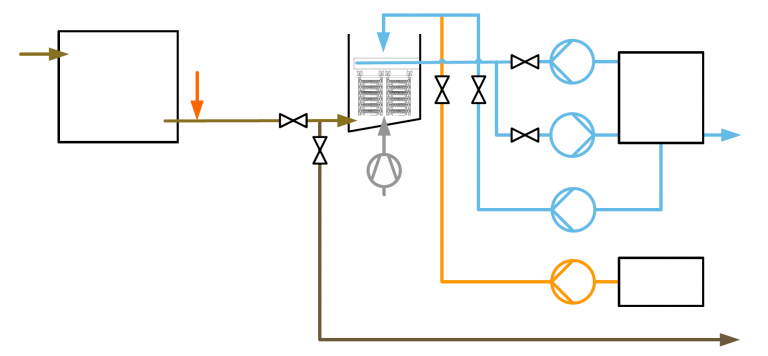
BLOWER FOR AIR-SCOURING

RETENTION TANK FOR CHEMICAL OXIDATION

TSE FROM POND

INJECTION POINT OF CHLORINE

CERAFILTEC WITH 1 TRAIN AND 1×2 TOWERS PER TRAIN

FILTRATION PUMP

SPRINKLER PUMP

BACKWASH PUMP

CAPCLEAN SPRINKLER PUMP

CHEMICAL PREPARATION TANK

INJECTION POINT OF ALUM

FILTERED WATER TANK

FILTERED WATER TO CHILLER

CONCENTRATED SLUDGE DISCHARGE

PERFORMANCE DATA (STATION 1)

The TSE comes from a soybean food processing plant. High amounts of remaining undegraded proteins and oil are daily challenges that can lead to rapid membrane fouling. Further, the storage of the TSE in the ponds increases the formation of algae. Both challenges are solved using CERAFILTEC’s process-integrated membrane cleaning function (CapClean). The membranes are fully recovered with each automated cleaning cycle using chlorine with a soaking time of 3 minutes. 

Consistently high flux is achieved by operating the system as active cake layer filtration (ACLF) in conjunction with frequent CapClean execution.

PARAMETERUNITFEED WATERFILTERED WATER
ColorPt-Co11739
CODppm6830
BODppm94
TSSppm18< 1 (nil)
TDSppm946967
TurbidityNTU11.2< 0.5
Oilppm7.2< 0.2
PARAMETERUNITVALUE
No. of trains1
Max. flow per trainm³/hr15.5
Max. flux rateLMH215
Filtration timehrs12 x 1.93
Backwash timesec12 x 30
Recovery rate%92.2
Power consumptionkWhr/m³0.04
ColorFeed water 117 Pt-Co
Filtered water 39 Pt-Co
CODFeed water 68 ppm
Filtered water 30 ppm
BODFeed water 9 ppm
Filtered water 4 ppm
TSSFeed water 18 ppm
Filtered water < 1 (nil) ppm
TDSFeed water 946 ppm
Filtered water 967 ppm
TurbidityFeed water 11.2 NTU
Filtered water < 0.5 NTU
OilFeed water 7.2 ppm
Filtered water < 0.2 ppm
No. of trains1
Max. flow per train15.5 m³/hr
Max. flux rate215 LMH
Filtration time12 x 1.93 hrs
Backwash time12 x 30 sec
Recovery rate92.2 %
Power consumption0.04 kWhr/m³

PLANT PICTURES (STATION 1)

CERAFILTEC_TSE_reference_case (0)
TSE pond and intake pump
CERAFILTEC_TSE_reference_case (5)
Skid-mounted filtration plant from local systems integrator
CERAFILTEC_TSE_reference_case (6)
Skid-mounted filtration plant from local systems integrator
CERAFILTEC_TSE_reference_case (8)
Completed plant by systems integrator
CERAFILTEC_TSE_reference_case (16)
Completed plant by systems integrator
DCIM107MEDIADJI_0009.JPG
Completed plant by systems integrator
CERAFILTEC_TSE_reference_case (21)
Feed water after coagulation inside filtration train
CERAFILTEC_TSE_reference_case (10)
Start of backwash
Cake layer removal
CERAFILTEC_TSE_reference_case (11)
Air-scouring during backwash mode
CERAFILTEC_TSE_reference_case (25)
CapClean during backwash mode
CERAFILTEC_TSE_reference_case (26)
Plant performance testing
CERAFILTEC_TSE_reference_case (33)
Filtered water (left)
feed water (right)
CERAFILTEC_TSE_reference_case (30)
Filtered water (left)
feed water (right)
CERAFILTEC_TSE_reference_case (36)
Filtered water for chillers
CERAFILTEC_TSE_reference_case (37)
Contaminated chiller prior to CERAFILTEC installation
CERAFILTEC_TSE_reference_case (42)
Contaminated chiller prior to CERAFILTEC installation
CERAFILTEC_TSE_reference_case (43)
Clean chiller with CERAFILTEC operation
CERAFILTEC_TSE_reference_case (41)
Clean chiller with CERAFILTEC operation